No products in the cart.
Easy to buy
Variety mode of payment
Easy to buy
Variety mode of payment
Free shipping
For orders from 3,000,000 VND
Support 24/7
Even outside working hour
Contact Ho Chi Minh City
Tel: (028).3977.8269 / 0906.988.447
Email: sales@lidinco.com
Contact Bac Ninh, Ha Noi City
Tel: (0222).730.0180
Email: bn@lidinco.com
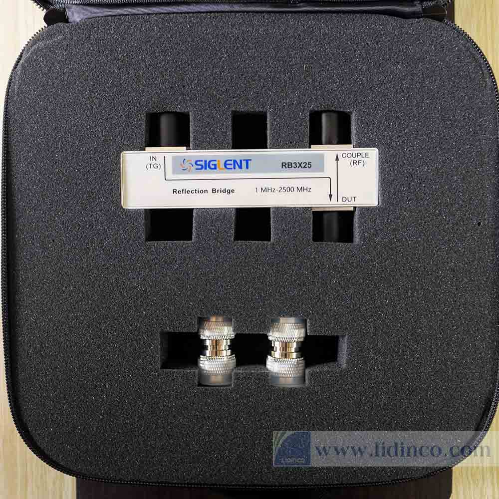
The Siglent RBSSA3X25 is used in connection with SIGLENT’s SSA3000X series of spectrum analyzers to measure S11-related parameters such as return loss, reflection coefficient and VSWR. The RBSSA3X25 also provide 2 N(M)-N(M) adapters to facilitate connection with the SSA3000X’s ports.
The reflection bridge has 3 ports as shown in the figure:
-IN(TG):Signal input terminal.This terminal connects to the TG terminal of the spectrum analyzer
-OUT(RF):Signal output terminal. This terminal connects to the RF input terminal of the spectrum analyzer
-DUT: This port is connected to the Device Under Test The distance between the SSA3000X’s TG and Input ports is designed to match that on the RBSSA3X25 in order to improve accuracy by eliminating the need for extra cables.
1.Connection
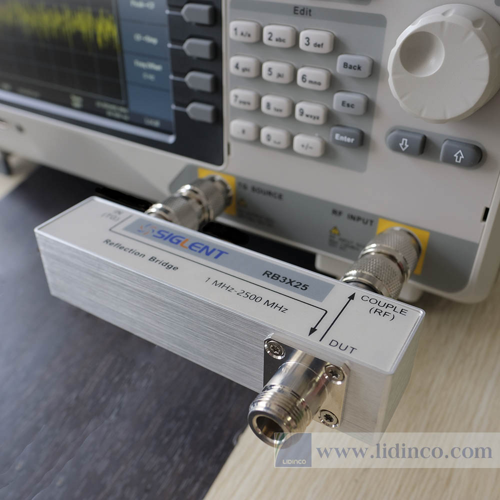
The connection of RBSSA3X25 and spectrum analyzer is shown in the figure to the right:
Use 2 N(M)-N(M) adapters to connect the output terminal of the tracking generator and the RF input terminal of the spectrum analyzer to the IN terminal and OUT terminal of the reflection bridge respectively.
2. Measurement procedure
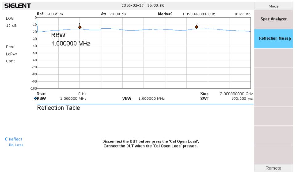
1) Press Mode -> Reflection Meas, to access the Reflection Measurement mode. The Tracking Generator and the Tracking Generator indicator light will activate and the screen will appear as below:
2) In the Reflection Measurement mode the user can modify certain spectrum analyzer parameters such as Frequency, Amplitude and BW, in those related menus.
User Manual
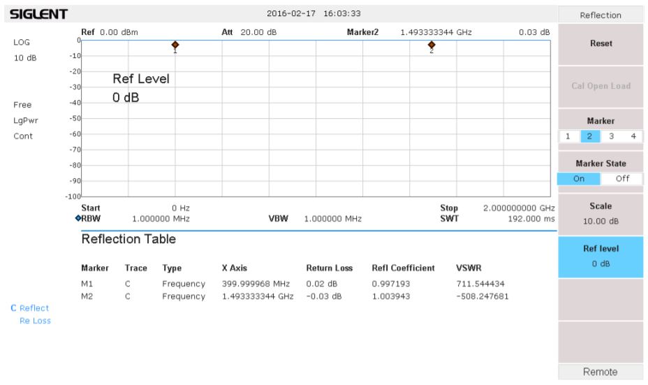
3) Connect the DUT terminal of Reflection Bridge with an open load, or leave it unterminated. Press Cal Open Load. The analyzer screen will now appear as below:
4) Connect the device under test with the DUT terminal of the reflection bridge. The cables or adapters between the DUT and bridge should as short as possible, in order to reduce extra mismatches. The resulting display appears as below. The trace on the screen is the return loss of the device under test.
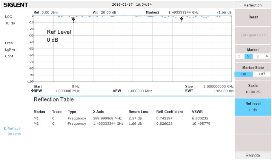
5) Press Marker, select a Marker (1-4), and Press Marker status ->On to open multiple Markers. Move the position of the Marker and the Reflection Table will display the frequency, return loss, reflection coefficient and VSWR at that Marker point. The Scale is used to set the value of the grid’s vertical scale. The Ref level sets the maximum value (top line) shown on the screen.
6) To quit the Reflection Measurement Mode, press Mode -> Spec Analyzer
| Frequency range | 1 MHz – 2000 MHz | |
| Connector type | N(Female) | |
| Impedance | 50 Ω | |
| Insertion loss | IN to DUT: 5 dB(typical) | |
| Directivity | 1 MHz – 2.0 GHz | 2.0 GHz – 2.5 GHz |
| 20 dB (typical) | 15 dB (typical) | |
| Size& Weight | 136 mm ×75 mm × 30 mm, 0.5 kg | |